Yesterday, I explained the basics of electrical circuits. If you missed it, you can read it Here.
Today I want to show you this concept in action. How it looks in real circuit and how to take measurements with multimeter.
Let’s start taking electrical measurements now.
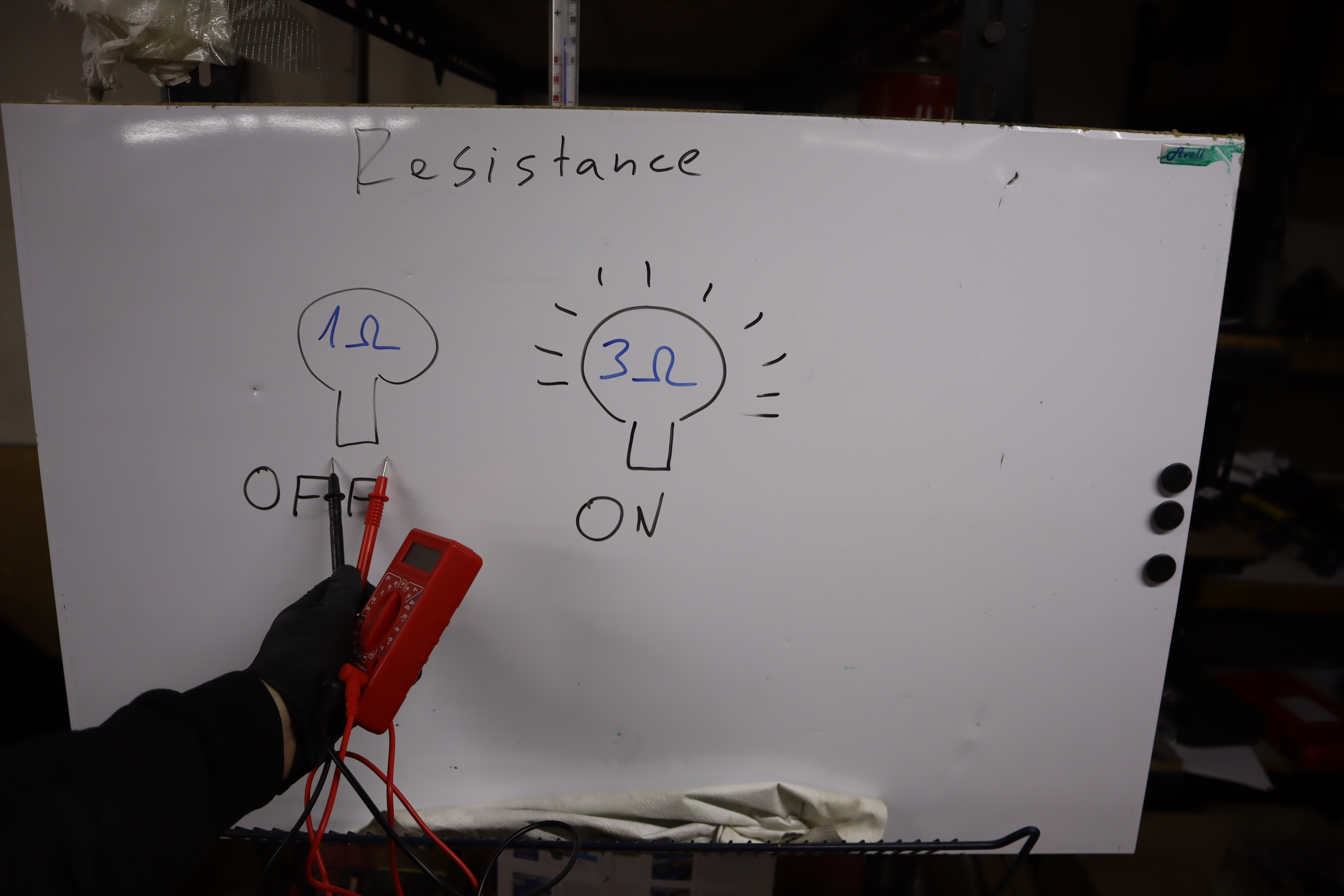
Resistance
You measure resistance with an open circuit, so the component is not working.
With the multimeter, place the black lead into the COM port and red lead in the Voltage/Resistance/Continuity port.
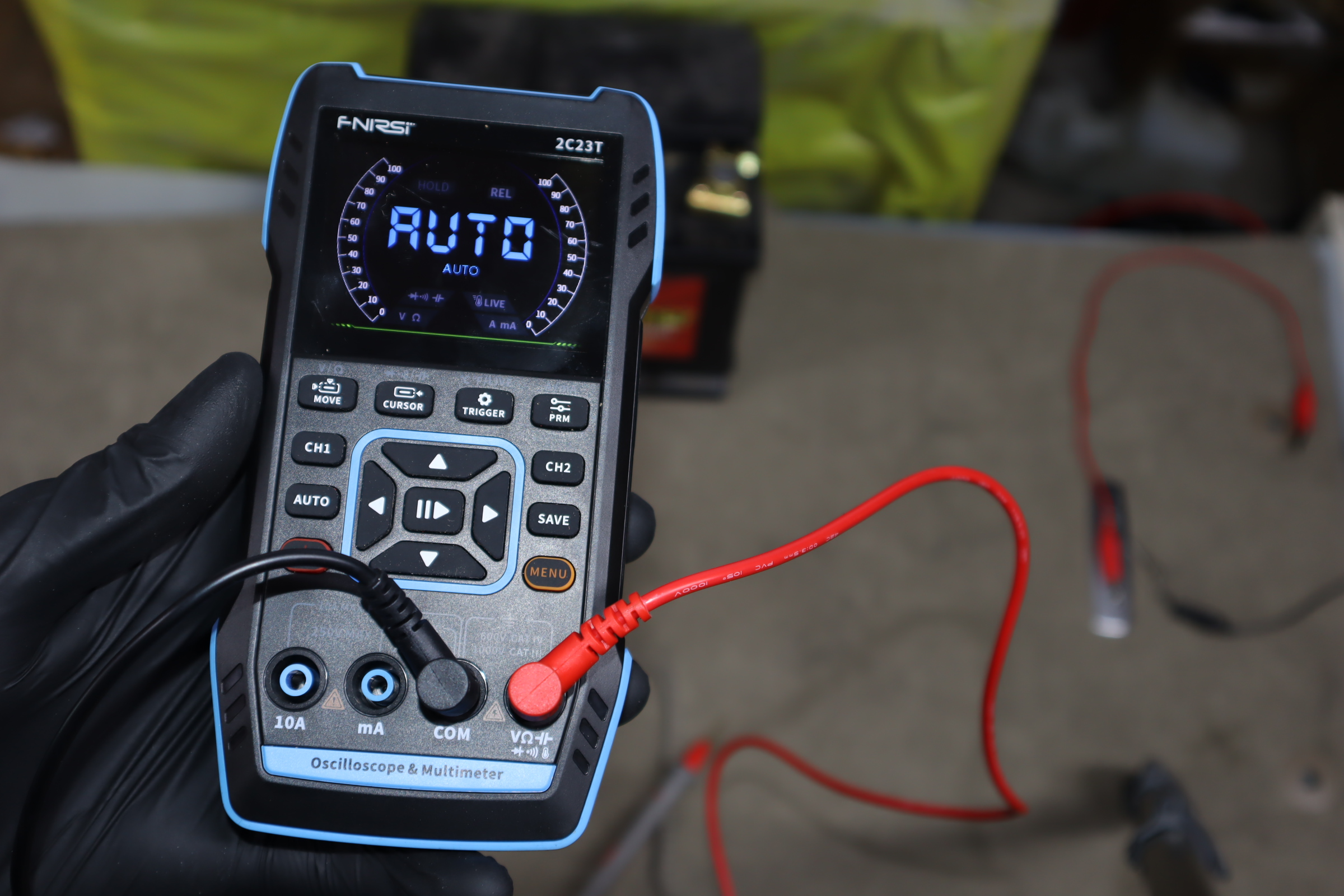
In case you are using a cheaper multimeter, you must also select the expected range.
This is another multimeter, I am placing leads in the same ports. 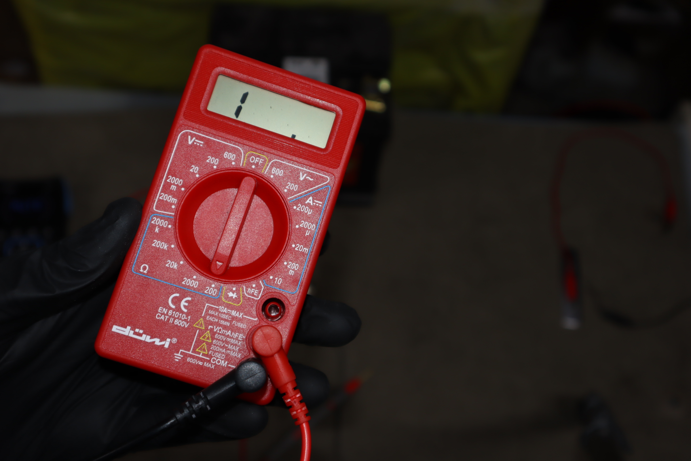
But this time I have to also select the expected range. I am expecting about 1-2Ω. The closest value to that would be the 200 Ω setting on this multimeter.
Now touch both terminals on a lightbulb with multimeter leads, and it will read resistance.
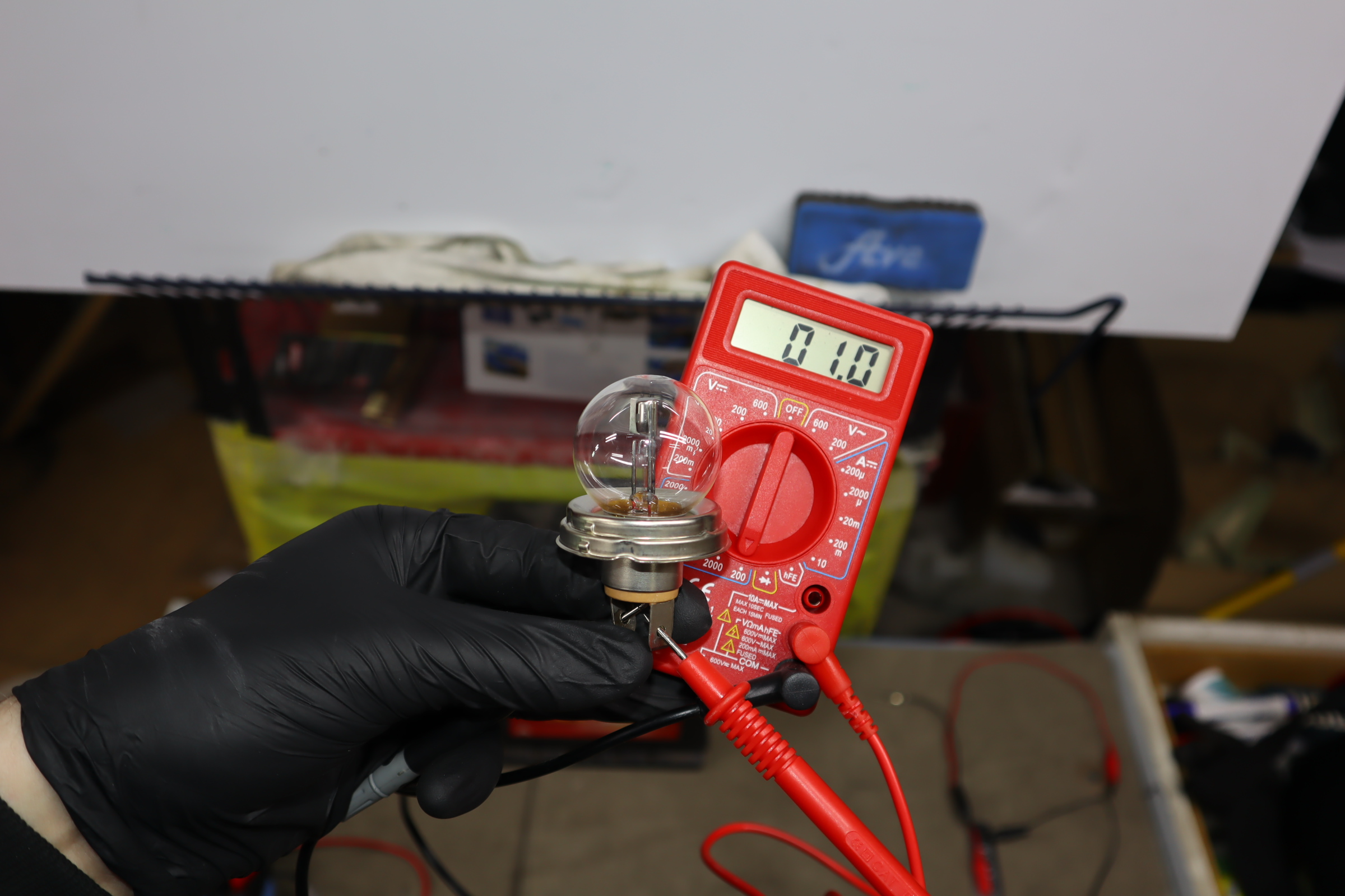
The lightbulb has 1Ω of resistance, but remember this will change once the bulb is in the operating circuit. Resistance will go up to around 3Ω.
Voltage
To measure voltage, leads must be in the same ports as when measuring resistance. If you work on a 12V circuit, select the 20V option on the multimeter.

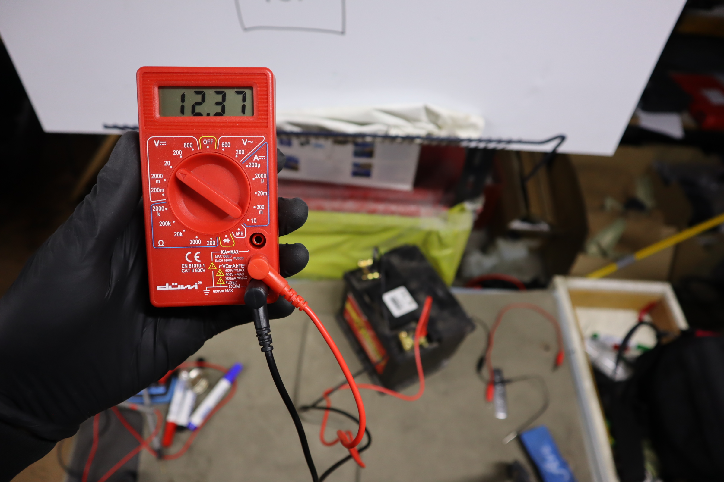
Place one lead on the positive (+) side and another lead on the negative (-) side to get a reading.
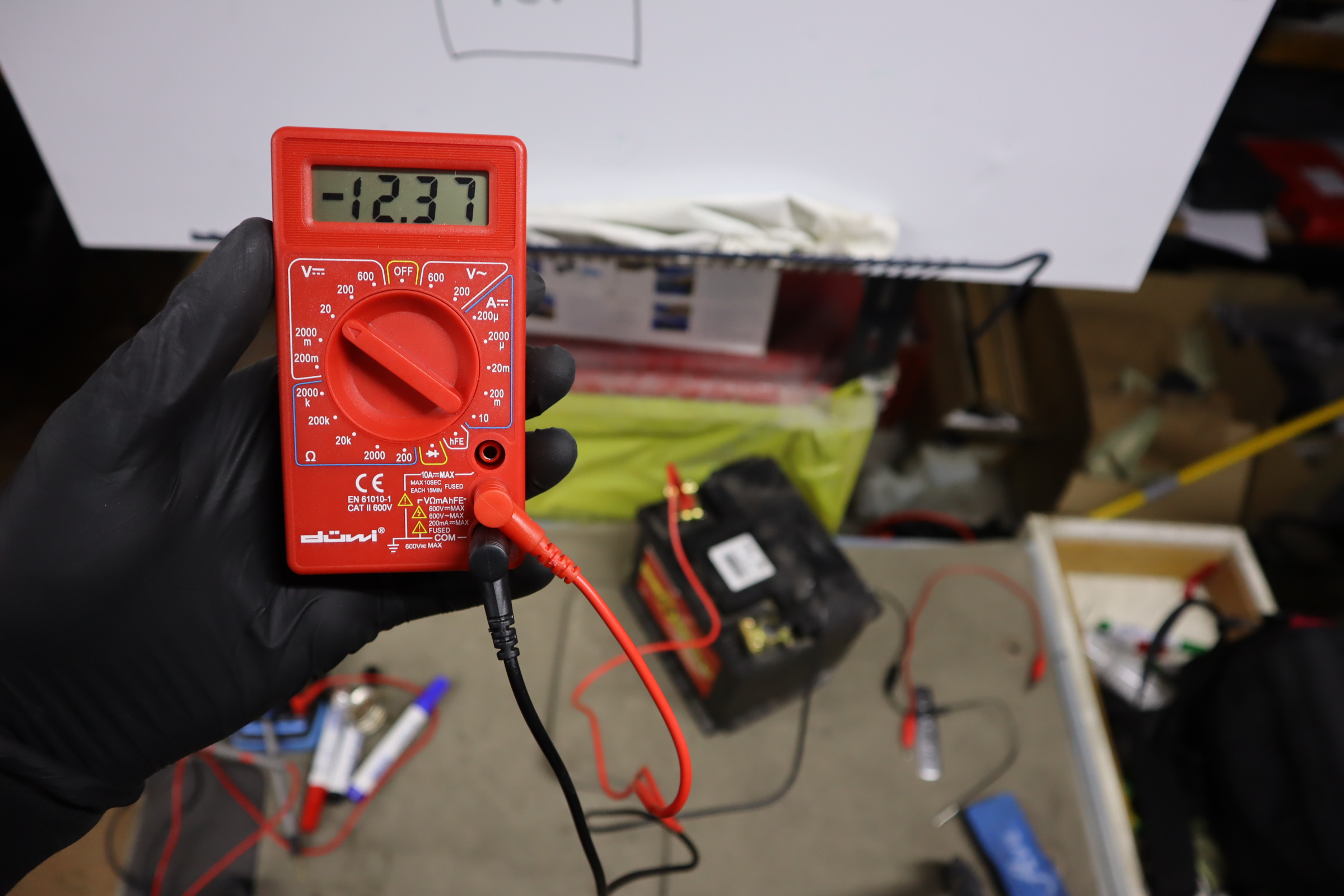
If you put your leads in reverse, nothing will happen; you will get same reading just with the opposite polarity.
When you measure voltage your multimeter take measurement of each lead and shows you the difference on display.
If I see 12V, it means the difference between the two leads is 12V.
The positive side has 12V and the negative side has 0V.
12V – 0V = 12V
It is important to understand this to avoid mistakes.
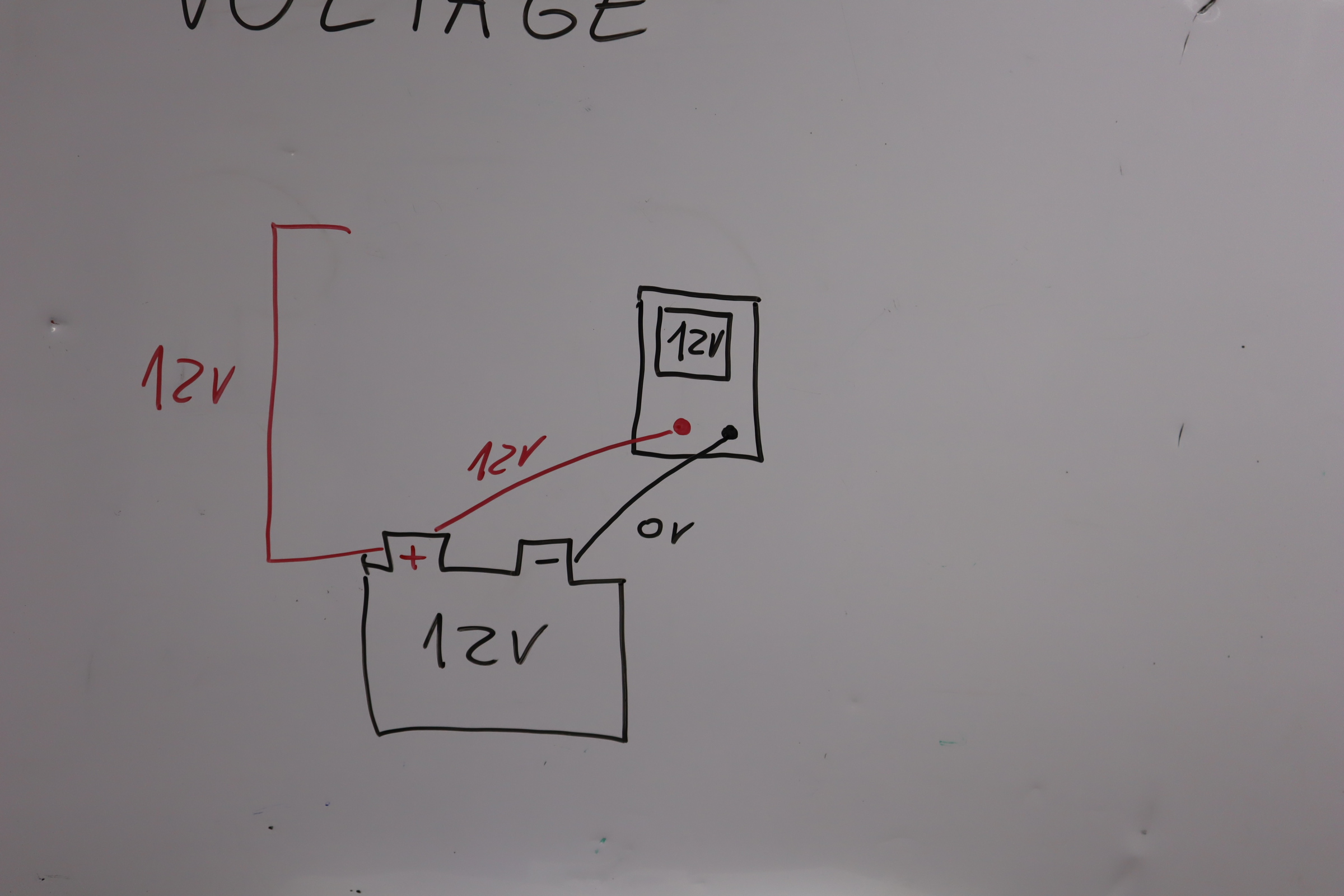
Check this example:
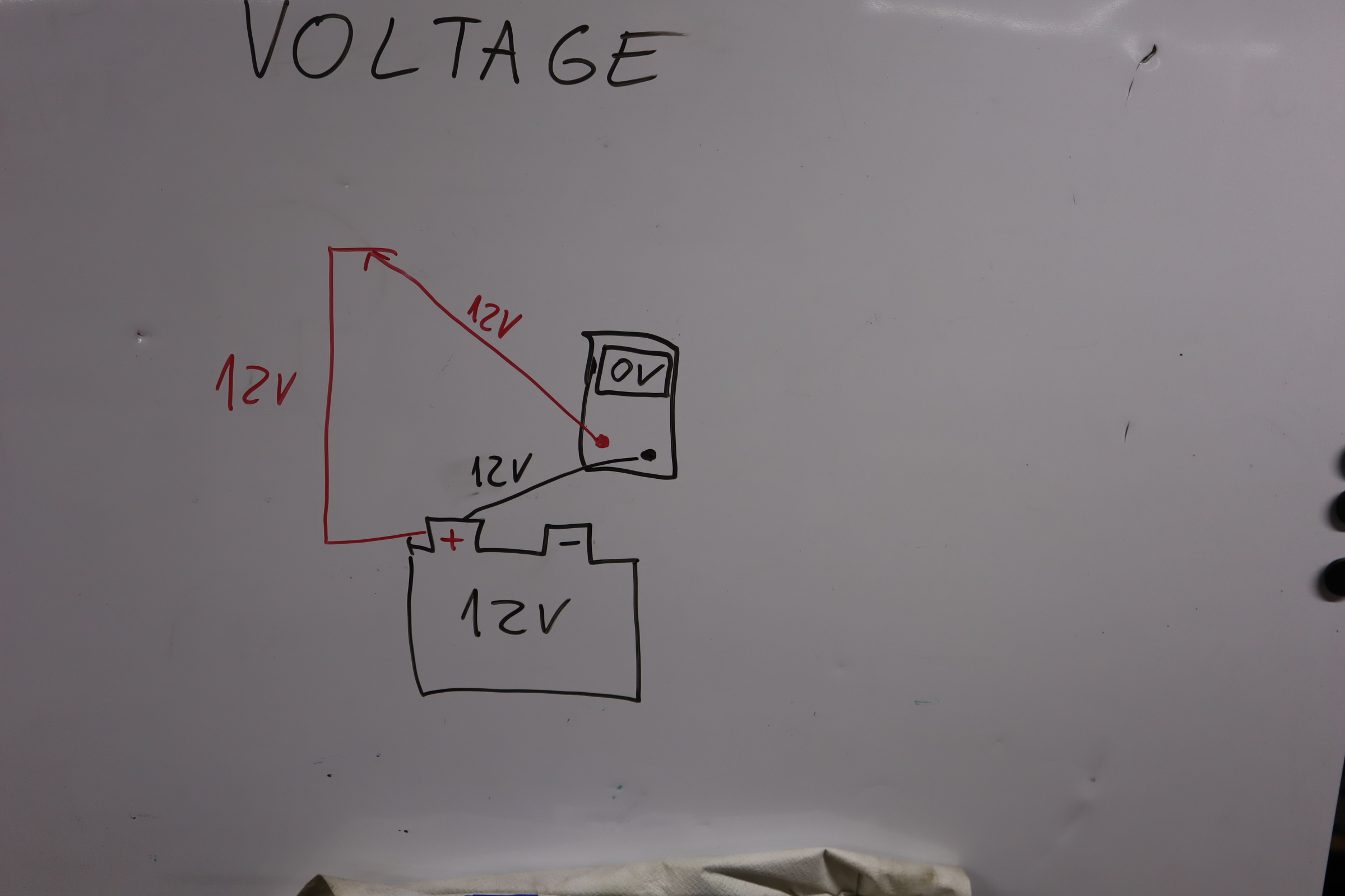
This wire connected to the battery has 12V. But since my red lead measures 12V and black lead measures 12V as well, the difference is 0V.
But it is still 12V on that wire, it just multimeter will always display a difference so 12V – 12V = 0V.
This is the correct way of placing leads to measure voltage on this wire:

Keep in mind that the Voltage will not be the same in the whole circuit.
If the circuit is open, voltage is present up to the end of the circuit.

Once the circuit is closed, Voltage will be used by the load. In this case lightbulb.

This will change when we will work with multiple loads in one circuit, but about that later.
This is enough to get you started.
BONUS: Try your first tests on your battery.
1. Measure battery voltage with engine OFF (good battery around 12.6V)
2. Measure battery voltage during start (shouldn’t drop below 10V for a good battery)
3. Measure battery voltage with engine ON (should be at least 13.5V if the alternator works)
P.S. The Extended version of this email course, including 60 video lessons to help you master DIY diagnostics, is available HERE.

Hi, I am Juraj “Yuri” Lukacko. I got frustrated by unhelpful and scammy mechanics, so I decided to learn everything about car diagnostics myself. I test dozens of new car diagnostic tools every month along with learning new strategies to fix and customize cars. About Juraj Lukacko (Yuri)